Optimizing Substation Controls Layouts
A substation steps up or down low voltage electricity coming from the power line to a higher level to enter neighborhoods, using power transformers. It also controls the operation of outdoor equipment.
To reduce noise inside a substation, this paper proposes an optimization method for layout design. The method utilizes a region growing algorithm to estimate the neighborhood power supply area for each substation.
1. Review the Existing Layout
Substations are high-risk environments with dangerous equipment that is often hidden from sight. The slightest mistake or accident can cause severe damage and downtime that affects the safety of people working inside and the flow of power to customers. A simple misstep could get someone too close to live equipment, an accidental flip of a switch can bring the facility to a halt, or a dropped wrench could trigger an explosion.
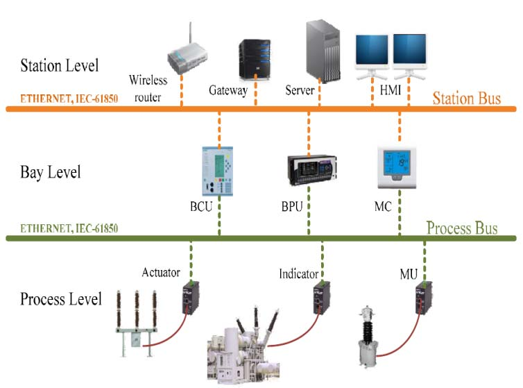
Substantially reducing the risks of these incidents requires an integrated, automated approach to substation operations. Substation automation integrates intelligent devices, control systems, and communication networks to enable centralized monitoring, data analysis, and remote control.
A telecommunications drawing shows the communications transport systems (including SCADA systems) that multiplex the substation’s individual communication circuits into a single transport channel and de-multiplex these circuits back to the utilities’ master dispatch control center. This can include fiber optic, microwave radio, 900mHz, power line carrier, copper DS3, DS1, DSN or twisted pair circuits.
2. Identify Potential Problems
A substation is a point where power lines are connected to each other and circuit breakers or switches control the flow of electricity between them. It includes transformers to convert between transmission voltages, power factor correction equipment like capacitors and reactors as well as circuit breaker or switch devices that connect and isolate lines for maintenance and fault clearance purposes.
To maximize substation performance, careful consideration must be given to busbar layout and sizing to minimize losses and ensure efficient power distribution. Additionally, different busbar configurations such as single bus, main & transfer bus or ring bus offer distinct advantages in terms of redundancy and maintenance accessibility.
The design should also take into account stress on the apparatus insulators and structures due to contemplated full load bus current. Lastly, a clear plan should be made for future expansion in order to avoid conflicts with existing structures and equipment.
Ensure that all major equipment is located within the same building for ease of operations and maintenance, especially if the substation is gas-insulated. Similarly, sufficient space should be reserved for HV isolation rooms to allow easy access to large equipment such as the transformers.
3. Analyze the Existing Layout
A key factor for power substation performance is the optimum arrangement of electrical equipment. Effective grounding and lightning protection systems protect equipment from electrical surges and minimize the risk of failure. Power substation design must take into account these factors as well as safety and maintenance access requirements when designing the layout of control house and other major equipment.
In a downtown city center location in Wuhan, reality modeling of the existing environment allowed the team to plan the substation layout including feeder cables with minimal impact on nearby buildings and infrastructure. Having the ability to share the 3D model and unified 2D electric protection and control schematics with a single tool reduced the time required for coordination, eliminated clashes between design from different disciplines, and enabled fast construction.
A power substation is a complex system of transformers, circuit breakers, switches, and other equipment that transforms high-voltage transmission lines into low-voltage distribution levels before it is transmitted to end users. Optimal substation layouts facilitate the transmission of electricity to ensure efficient and reliable operations. Whether the substation is a transmission or distribution level, the optimum arrangement of busbars should be considered to maximize power flow and ensure the proper breaker sequencing.
4. Create a New Layout
Power substations are a crucial link in the power supply chain. They facilitate voltage transformation between transmission and distribution levels, ensuring efficient and reliable power delivery to consumers.
A typical power substation includes a transformer to convert the power, high-voltage switches that connect or disconnect lines, and control systems (power control cables) to regulate and protect the system. These substation control systems can be automated or operator-driven.
Traditionally, these systems relied on low-bandwidth communication links which limited the amount of information that could be sent and received. However, rapid advancements in communication and processing technologies have turned digital devices into intelligent units that can send and receive a much larger amount of data.
Substation design is complex and requires coordination between multiple disciplines such as site preparation, electrical, mechanical, and protection. PESTECH realized significant benefits from digitalizing this process including requiring less than seven working days for schematic drawings, reducing the time needed to create cable schedules by more than 50%, and minimizing component wastage by 10-20%. This also led to faster project delivery and improved customer satisfaction.
5. Identify Potential Problems
As demand for power increases worldwide, mastering the intricacies of substation layouts is critical to ensuring reliable electricity supply. This can be accomplished by using advanced generative design technologies to streamline the planning and conceptual design process while minimizing costs, risks and environmental impacts.
Traditionally, limited data points on each device and the cost of communication made it impractical to collect a large amount of nonoperational data from every substation. As a result, only operational data was sent to control centers.
The proposed fault detection model uses a time series and SPC model to detect the status of the two switching processes in the substation. If an error is not within the determined interval, it can be classified as a singular error. The 3s criterion is used to conduct the singularity discriminant detection, and it is shown that this method can accurately diagnose the health of the substation with high accuracy. Moreover, it can be applied to the monitoring system to detect abnormal conditions and prevent faults. Using this approach, the overall maintenance costs of the substation can be greatly reduced.